Since it has rained so much this winter and prevented me from flying I have had to find other hang-gliding related activities to occupy my time. One of those was studying for and gaining my Amateur Radio (HAM) Technician's license. In fact it is ridiculously easy to get the license - a simple multiple choice test of 35 questions of which you need to get 26 or more correct. There is no morse code requirement for the Technician license and it is all you need to legally operate on the 144~148MHz (2M) radio band that is used by hang-gliders (you can do much more, but hang-gliding is what I'm interested in). I found a good set of training slides (Powerpoint) online which I studied over a couple of days (I'm already an Electronic Engineer so I have a bit of a built in advantage). Then I spent some time practicing with a free online test. I was lucky to find that a test session was scheduled not far from me for the very next weekend. It cost $14 to take the test and I scored 100%. Now I have call sign KI6DLU.
The ink was not yet dry on my new license when I went and purchased a Yaesu VX-150 2M Hand-held Transceiver (schematic). This is a really nice little radio, it receives from 140~174MHz and transmits over 144~148MHz. It is almost exactly the same as my Vertex Standard ProV air band transceiver and in fact shares the same battery pack and recharger. It only cost about $130 which is less than half what I paid for the ProV. Its small and rugged and should fit nicely into my harness hip pocket. It also came recommended for hang gliding here. To use a radio when hang gliding you need a headset that fits inside your helmet and you need to be able to operate the PTT (Push To Talk) switch while still flying. So people have developed hang/para-glider headset/PTT combo's that plug into the radio. However, I found that such an item cost $75 at my local hang gliding emporium which seemed a bit steep considering the whole radio was only $130. As I've been known to man-handle a soldering iron from time to time (and it was still raining) I decided to build my own. The directions below assume you have some basic electronics knowledge and you will need to be good with a soldering iron as the connectors are not the easiest to solder (especially the one that plugs into the VX-150). |
Parts List
| Mouser Part Num. | Description | Qty |
Price |
Total |
| 253-5221 | Kobitone Speaker 8 Ohm 0.87" 1.1W | 1 |
$2.99 |
$2.99 |
| 25LM042 | Kobitone Condenser Microphone 5.4x6.5mm | 1 |
$4.71 |
$4.71 |
| 101-TS6424T2601-EV | Mountain Switch Tactile Switch 12mm Square 260gf Red Surface Mount | 1 |
$0.76 |
$0.76 |
| 17PP004-EX | Kobiconn
3.5mm Stereo Phone Plug Black |
2 |
$1.11 |
$2.22 |
171-6435-EX |
Kobiconn
3.5mm 4-Conductor Right-Angle Phone Plug Black Kobiconn 3.5mm 4-Conductor Right-Angle plug with 6' black cable |
1 1 |
$1.74 $4.49 |
$1.74 |
| 172-3535 | Kobiconn
120" Audio Cord 3.5mm Plug to 3.5mm Jack Black |
1 |
$3.29 |
$3.29 |
| 30BJ250-2.2K | 1/4W 2.2K Ohm 5% Carbon Resistor | 1 |
$0.22 |
$0.22 |
| Total for Mouser: | $15.93 |
|||
| Frys Electronics | 3.5mm Stereo Headphone Splitter (available many places) | 1 |
$2.99 |
$2.99 |
| Rip-Tie Cable Wrap 1" x 9" Black 3-Pack (expensive - can't find at Fry's anymore 8/2010) | 1 |
$9.49 |
$9.49 |
|
| Heat Shrink Tubing Kit, 154pc 4" Lengths, Assorted Colors (if you don't already have some) | 1 |
$8.99 |
$8.99 |
|
| Total for Frys: | $21.47 |
|||
| Home Depot | 3/4" Adhesive backed Velcro Strip (I can't remember what it cost - but not much) |
Electrical
Diagram
 |
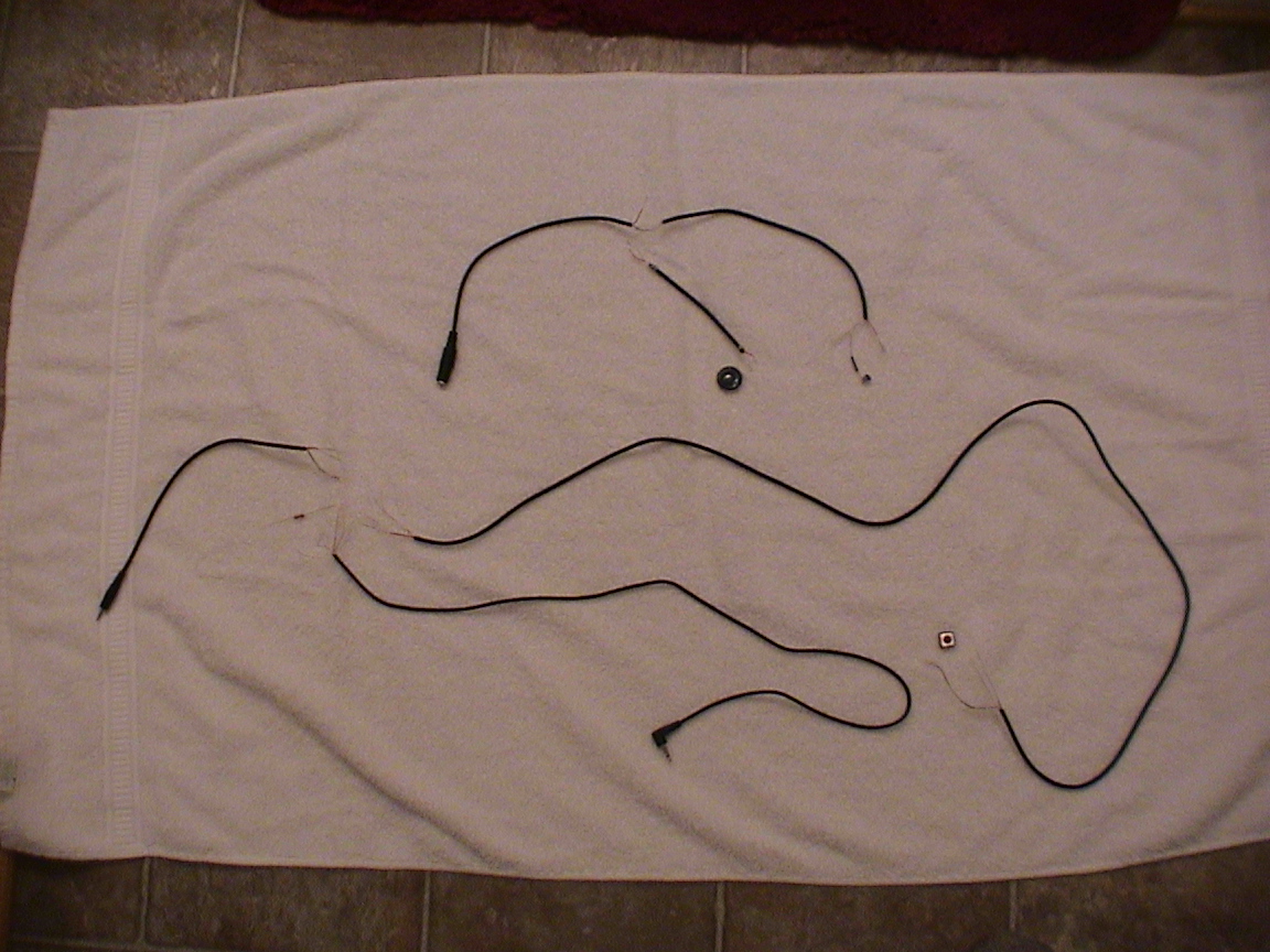
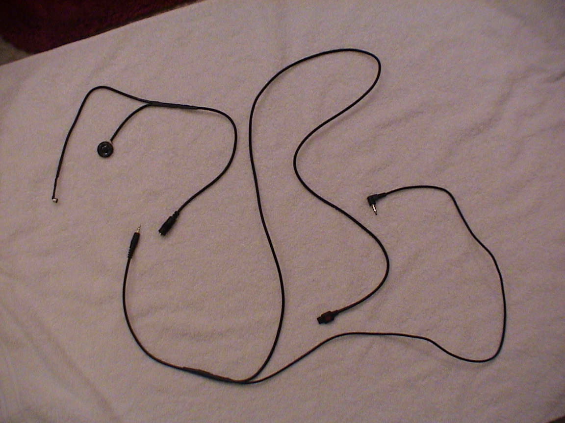
This project consists of three separate bits; the headset, the PTT switch and the radio connection. All three pieces are joined together at a head-phone splitter that is stuck (with velcro) to the side of your helmet. This design keeps the radio and PTT wires separate - so it doesn't feel like you're wrapping a wiring harness around yourself getting everything connected. |
This design works with the Yaesu VX-150 radio and a full face helmet. It should also work with the Yaesu VX-170 radio and I've included some information at the end explaining the difference. It might work on other Yaesu HAM radios or it might not and it might cause them to explode, your head to explode or both at the same time. Also electronics is a dangerous pastime that involves red-hot soldering irons, corrosive toxic solder and flux fumes that contain lead which is known to the State of California to cause something bad. You may grow an extra head just thinking about all the bad stuff that could happen. So you have been warned, if you blow-up you radio, you head or anything else it is not my fault.

Headset Construction
The 120" audio cord supplies all the dual core coax we need for the project and the nice molded 3.5mm inline jack (socket). Start by determining how much cable you need to reach from where your ear will be inside the helmet and the outside of the helmet where you will mount the inline jack. Remember it is far easier to cut wire then to add it so leave a little extra length, you can always push it inside the helmet lining, cut the length you need. Then measure out how much cable you need to reach from your ear around the inside of the helmet lining to your mouth, again cut to length but keep it on the long side.
The cable will have two cores (because it is stereo cable), in the one I bought one was colored red and the other white, the white one was connected to the tip of the plug and the red was connected to the first collar. Refer to the electrical diagram above, the wire that connects to the tip is used for the speaker, and the wire that connects to the collar is for the mic. It is important to keep this all consistent - speaker wire (white) always goes to the tip and mic (red) always goes to the collar (and of course shield always goes to the common). Your colors may differ, so check it using a ohm meter or a multi-meter or some other continuity checker. The easiest way is to check the plug on the audio cord against the exposed wire (since you cut it) at the other end.
 |
 |
 |
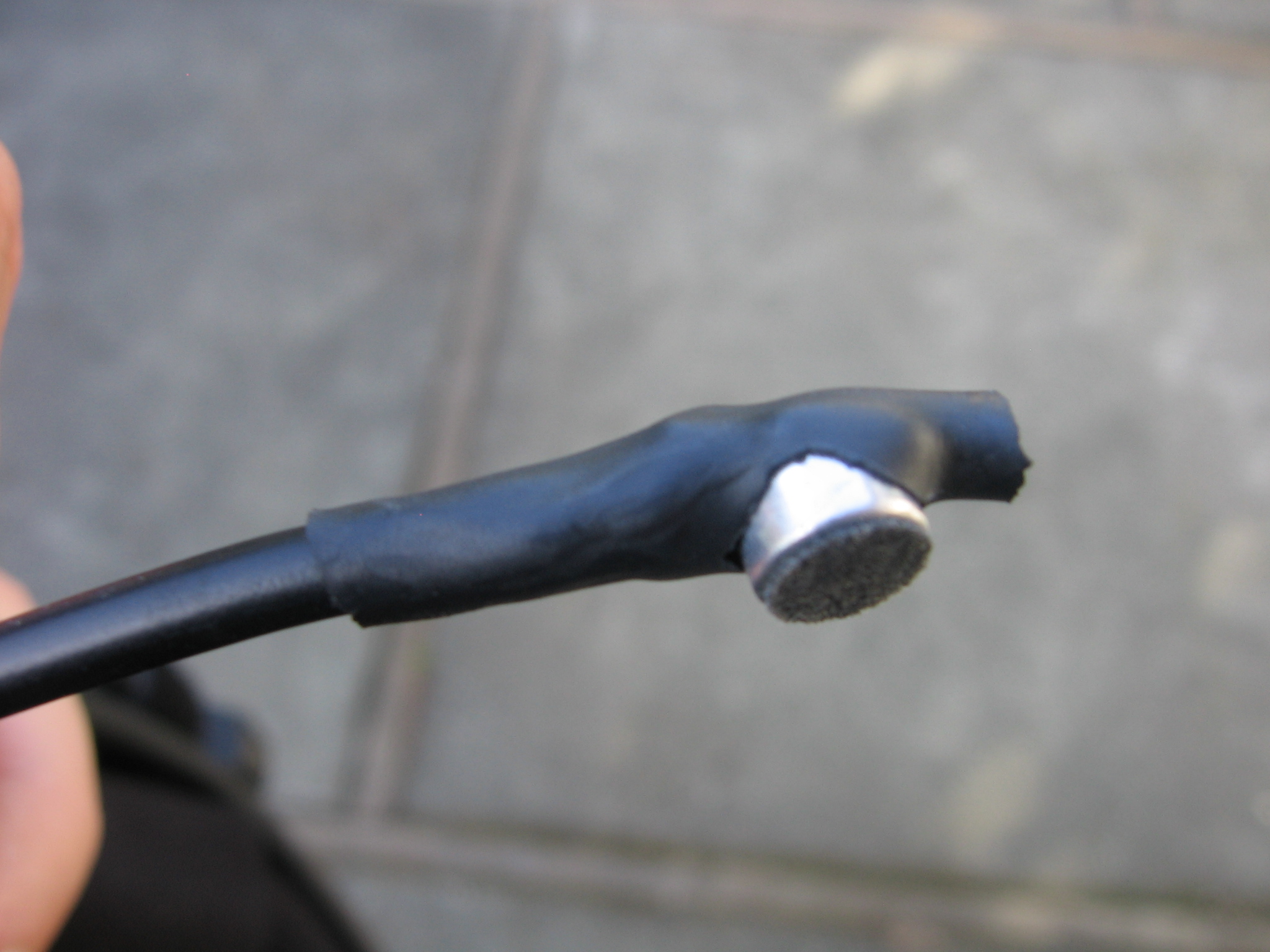 |
Using the construction diagram above, solder the microphone to one end of its cable, even though there are two core wires just use the mic wire (red) and the shield to connect to the two terminals of the microphone (Cut the speaker wire (white) off where it appears past the shield to avoid mistakes soldering the wrong wire). Cut a notch out of a piece of 3/8" heatshrink tube as shown, slip it over the microphone and cable until the microphone pokes through the notch. Then heatshrink the tube to that it holds the microphone firmly and protects the solder joints on the bottom. It should look like the picture to the left. Now slip a 2" long piece if heat shrink over the ends of the cable from the microphone and the inline jack (you won't be able to get it on later). Then solder the shield of both cables to one terminal of the speaker. Solder the speaker wire (white) from the inline jack to the other speaker terminal. Then solder the mic wire (red) from the microphone to the mic wire (red) from the inline jack. Slip a short piece of 3/16" heatshrink tube over this connection and shrink it so that it can't short to anything. Then cover everything with the 2" piece of 3/8" heatshrink tube and shrink it to pull everything together and protect as much of the soldering as possible. |
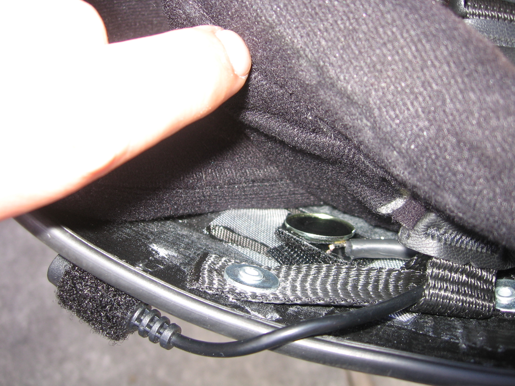
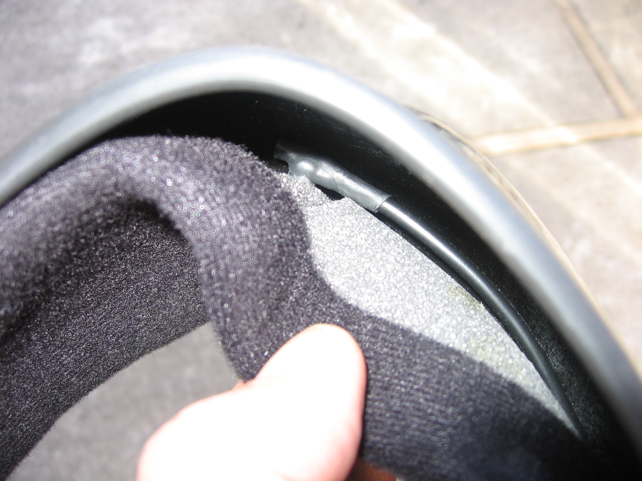
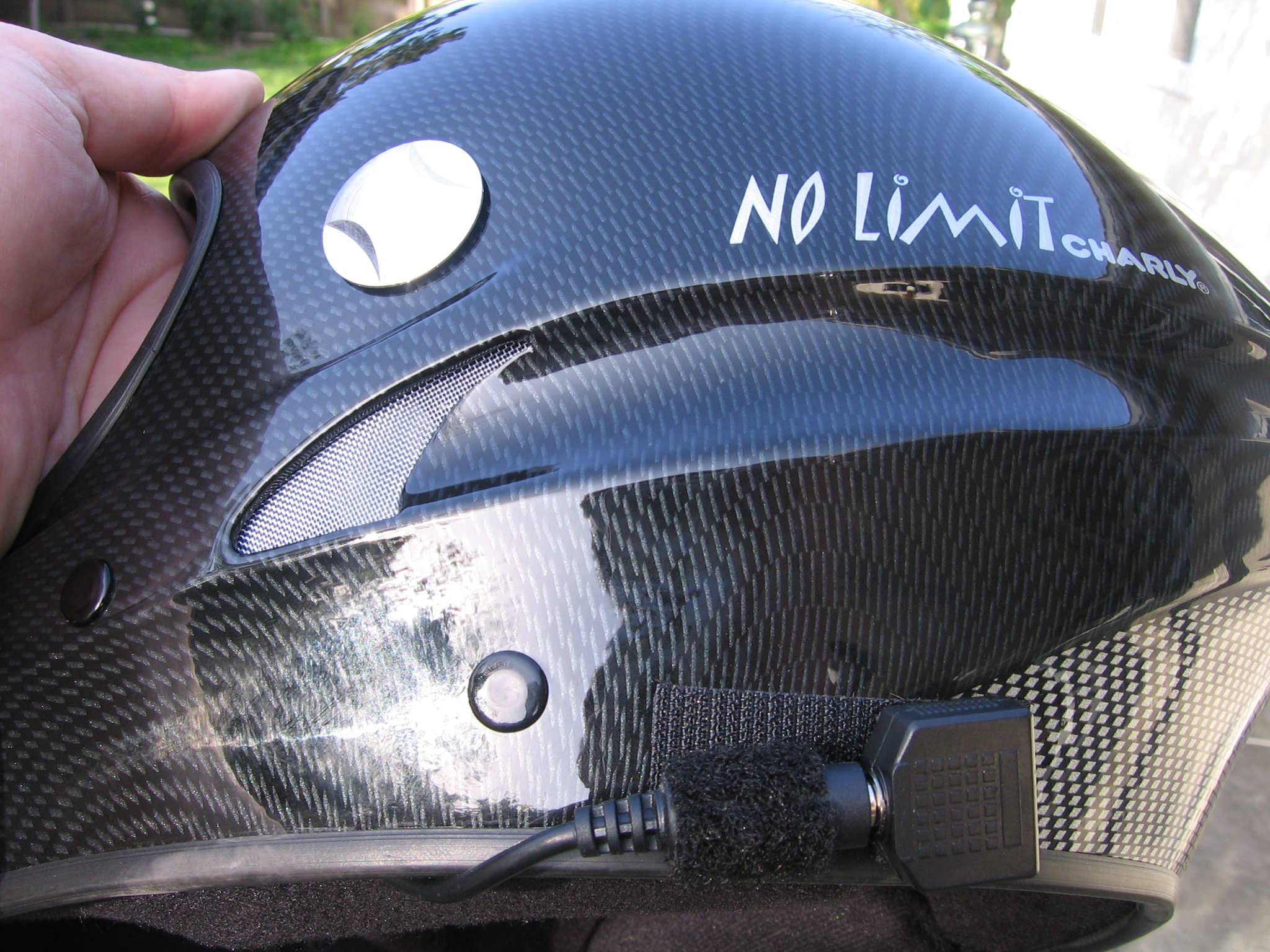
Using the adhesive backed velcro cut a small 1" long piece of the felt side and stick it to the back of the speaker. You want it to cover all the exposed metal connections and also stick to the end of the heatshrink tube as this will provide some strain relief. Now cut a matching piece of the hook side and stick it to the inside of the helmet (inside the lining) in the location where you wish to mount the speaker. In my Charly No Limit helmet I was able to gently pull the lining away and lay the wires inside, there was even a cutout in the foam for the microphone in front of my mouth (top middle picture). I threaded the inline jack through one of the loops where the chin strap attaches to the shell (top left picture) so that it wouldn't "wander" around. Finally, cut a length of the velcro felt and stick it around the inline jack and another piece onto the headphone splitter. Lastly mount a 2" long piece of the velcro hook side to the outside of the helmet to attach the inline jack and the splitter as shown in the top right picture.
PTT Construction
The PTT operates by connecting a 2.2K Ohm resistor between the mic wire (red) and the shield. 2.2K Ohm is particular to the VX-150, other radios use different value resistors. As the PTT switch needs to be a thin as possible, I decided to mount the resistor inside the 3.5mm stereo plug that connects into the headphone splitter.
 |
 |
 |
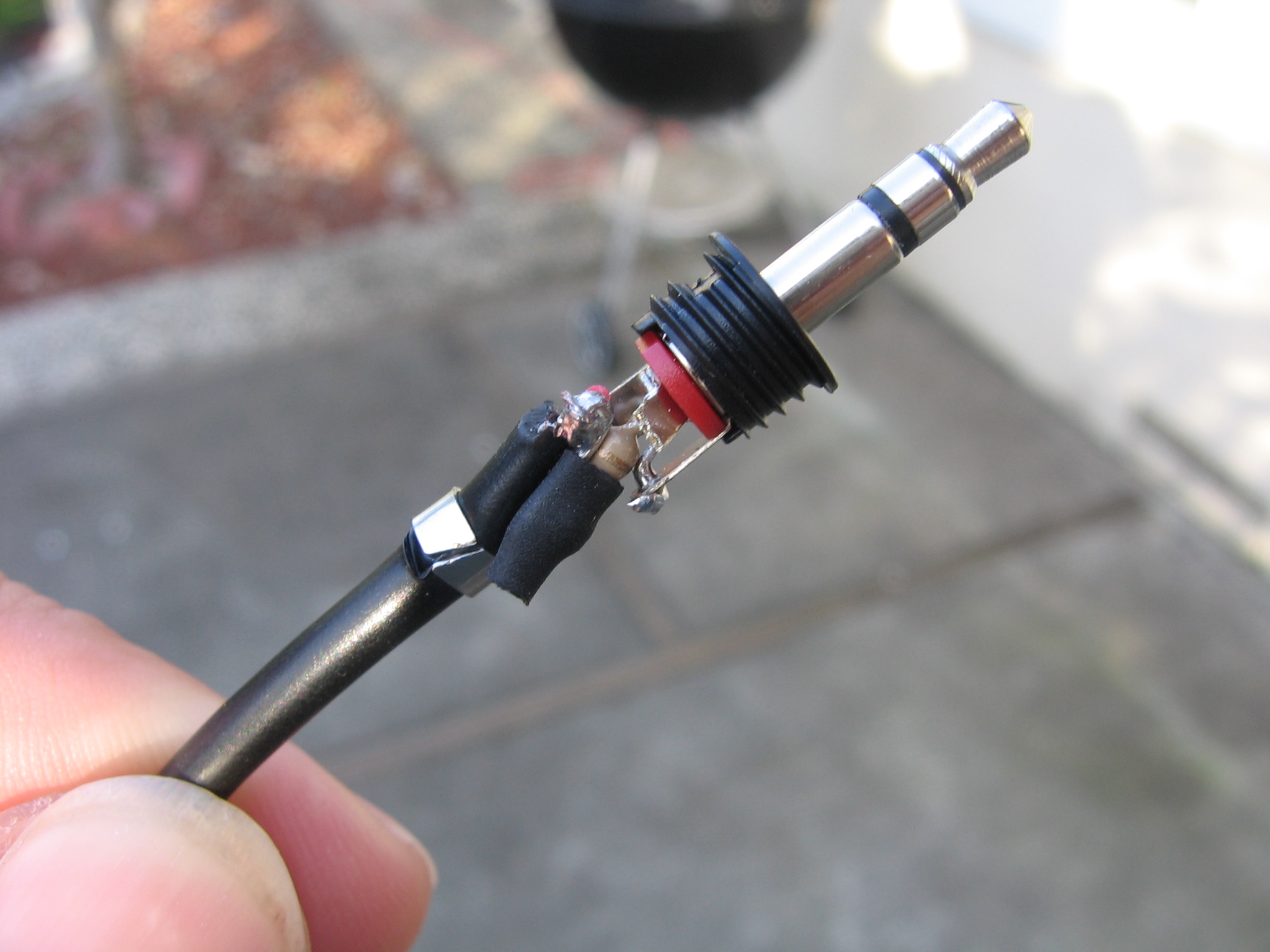
The picture on the left shows the mic wire red connected in series with a 2.2K Ohm resistor to the collar of the stereo plug. I used a small piece of heatshrink tube to cover the resistor as much as possible to stop it shorting and I cut off the solder lug for the plug tip for the same reason. Once this plug is connected, put on the helmet, plug it into the splitter and then carefully measure out the length of cable you need to reach your index finger. You might want to do this with your harness on, just to be sure you leave enough length to route the cable just how you like. Remember, always leave a little extra length.
The construction diagram shows some detail on soldering on the PTT switch. Don't forget to slip a 2" long piece of 3/8" heatshrink tube on first before you solder on the switch, you won't be able to get it on later. Then strip enough of the insulation to be able to solder both the mic wire (red) and the shield to both sides of the switch.This is not essential, but it will make the connection stronger which is important because this joint will see a lot of pulling and strain. When the soldering is done, push the heatshrink up OVER the terminals as far as it will go. You want it to be stretched over the switch terminals after you shrink it.
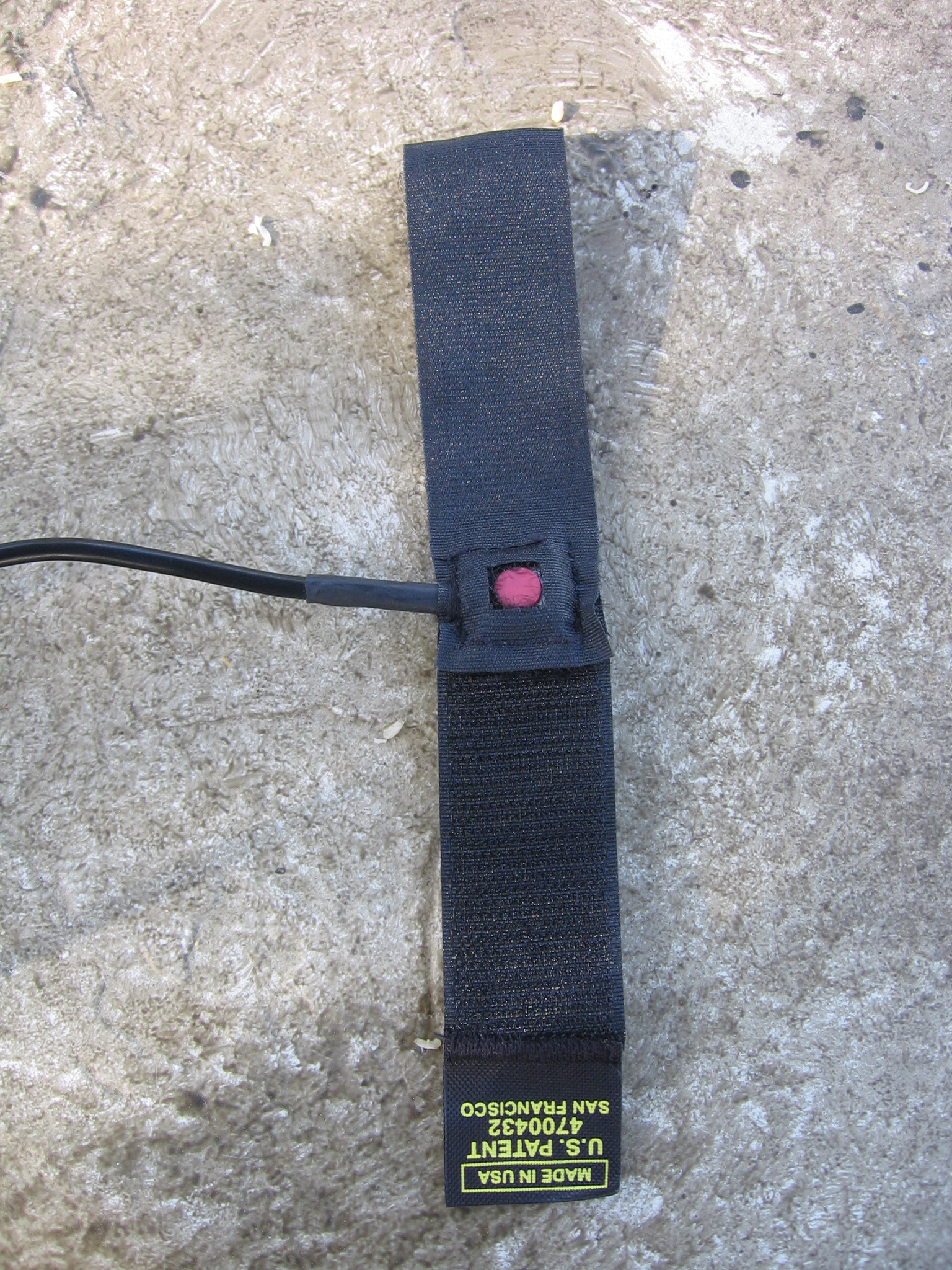
To make the velcro "ring" for your finger you just need 1" x 3.5" of velcro hooks and a 1" x 3.5" piece of velcro felt. I used a Rip-Tie because I had it laying around, but any piece of velcro will do. Overlap the pieces as shown in the middle picture hooks up, felt down, with enough overlap to sandwich the PTT switch between the two. Make a cutout in the felt piece for the actual PTT switch (red circle in the picture). Then sew the two pieces together around the edge of the PTT switch. Start sewing on the side where the cable emerges and make many loops of thread completely around the cable/heatshrink tube as tightly as you can to create a strain relief. It should end up looking like the picture on the right.
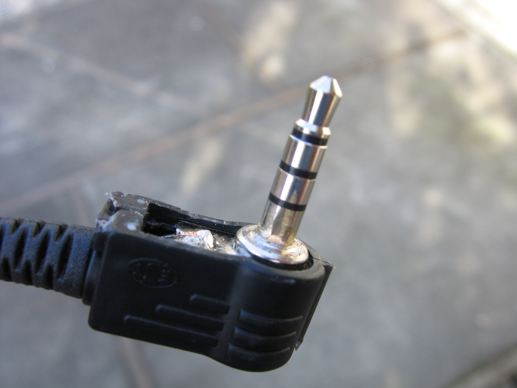 |
Radio Connection Construction Update 9/14/2007: A better solution (Thanks Steve!) than the one I used below is to just buy the 4-conductor plug with an integrated cable attached from Mouser and then just solder a standard 3.5mm plug on the other end of the cable after cutting it to the right length. The mouser part number is 172-7436. According to Steve, the plug is a better fit for the radio and you don't have the problems I talk about below. Old Instructions: On one end solder on the standard 3.5mm plug. Both core wires must be connected, the speaker wire (white) to the tip and the mic wire (red) to the collar. Then put on your harness and helmet, plug in the radio connection to the splitter on the helmet and measure out the length of wire needed to reach the radio wherever you plan to put it in your harness. Remember to leave a little extra length as usual. Soldering on the 4-conductor right angled plug is finicky, refer to the electrical diagram above to make sure you connect it correctly. Lastly, it appears the the connector used by Yaesu on the VX-150 is not EXACTLY the same as the one purchased from Mouser. The Yaesu needs to be slightly longer. Look carefully at the picture on the left. You can see the marks where I filed away a small metal step at the base of the plug to allow the plug to reach further into the socket. I also carved away a little of the plastic to get the plug into the radio socket as far as possible. If you experience intermittent operation of the PTT that goes away when you push the plug into the radio, then the problem is the plug is not inserted far enough. |
VX-170 Radio
 |
It seems like the VX-170 is the new radio of choice, I've seen a bunch of them around the LZ and recently a fellow pilot asked me for some help getting a headset to work with his new VX-170. That gave me a chance to check-out how its wired and determine how a headset should be wired to work with it. The VX-170 seems to be a next generation from the VX-150. Its a little bigger, has more memory, a better display, a much better battery pack offering 1400 mAh with NiMH batteries versus 700 mAh for the NiCd batteries in the VX-150. And its waterproof! As it stands the VX-170 uses the same 4-connector 3.5mm socket for an external mic/speaker as the VX-150. The socket is wired the same in both. So you could use the headset/PTT described above WITHOUT modification. However, the VX-170 uses a specialized socket that has a screw-in seal that keeps it waterproof. You could plug in the standard 4-conductor plug from Mouser and it may work but I'm concerned with the fact that the Yaesu plugs seem to be a little longer than standard. I recommend instead that you get the optional CT-91 mic adapter and then modify the Radio Connection cable as shown below and simply connect that to the CT-91. The diagram below should be all you need to get a headset/PTT working with this radio.
|

Added 1/19/2008
Here are some pictures from Steve Prater in Arkansas on the PTT he built using the plans on this page.
 |
 |
 |
Parts |
Cut
& Ready |
Finished |
Added 4/13/2009 - VX-170 Variant
I had a request for a variant on the VX-170 radio where only the microphone and PTT were required. In this case the speaker would be a completely separate pair of molded earbuds. With the CT-91 adapter on the VX-170 radio this is pretty easy. The separate earbuds go directly to the 3.5mm speaker socket on the CT-91 adapter. I'm not sure if the CT-91 has a stereo or mono socket. If its stereo but one channel is unconnected then only one side of your earbuds will work (someone let me know if that's the case). The diagram below shows how the microphone in the helmet and the PTT are constructed. Its very similiar to everything shown above so I hope it's self explanitory.
Added
8/29/2010 - VX-170 variant with battery saving feature
The diagram below is a modified version of the mic/PTT only circuit shown above. It was adapted from this circuit by Josh Widen. The condenser microphone I specified contains a small amplifier circuit (datasheet) that is powered from the radio. In my version, that amplifier is powered on all the time, it's maximum current consumption is 0.5mA, so while it's small it's not insignificant. In the circuit below, the PTT switch actually connects the mic to the radio when it pressed, therefore the mic only receives power when you are talking.
